Vibration Attenuation
PID Damper
Inspired by Gravity®
Patent US9521753 B1
PPT:  English   •   2 Minute  Video     Part Order Numbers  •  Catalog  •   NASA Technology Transfer  •   FAQ

Attenuate harmful PCB vibration with Particle Impact Damper PID components.

Inspired by Vibration®

Call to Order 1-800-776-9888   •   Catalog   •   Watch 2 minute video

Problem: Harsh vibration at fundamental frequency fo causes premature component failure and damage to Printed Circuit Boards (PCB) assemblies.

Solution: Surface mount a PID (Particle Impact Damper) on your PCB assembly. The PID component extends hardware life. It is a lighter, simpler solution, reducing the need for redundant systems. After vibration hardening, old hardware is ready for new missions in new operating environments.

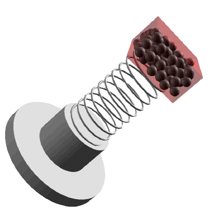
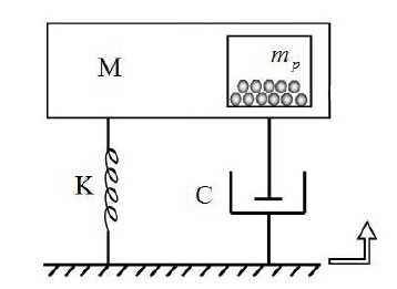
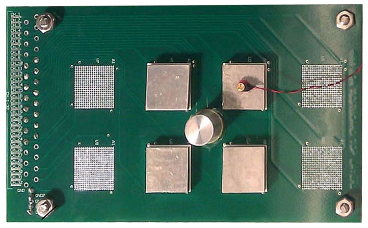
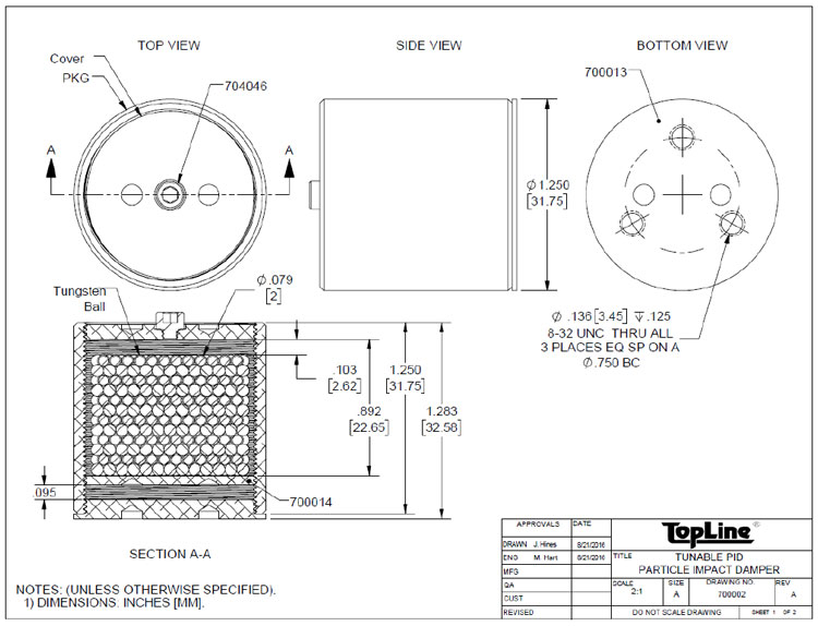
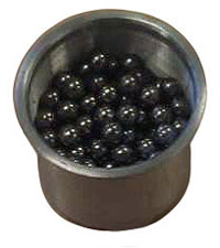
How:  The PID is housed in a sealed container that is filled to 90% with tungsten (Wolfram) balls. The counterbalance impact of tungsten balls in the PID dampens fundamental frequency fo mode vibrations in the PCB assembly. This maximizes energy transfer to the PID which dampens vibration. The weight of the tungsten inside the PID is approximately 10% the mass of the PCB assembly.

Where: Place the PID component near the geometric center (anti-node) of the PCB. The damping effect attenuates vibration and increases board assembly reliability. The PID may be located on either side of the board.

Alternatives:  The PID may be attached to an optional interposer bridge to straddle existing high density components on the board.

Fun facts:  Tungsten (W) is environmentally friendly. Tungsten's properties include high density and extreme tensile strength. The PID can fully function at extreme temperatures without derating.

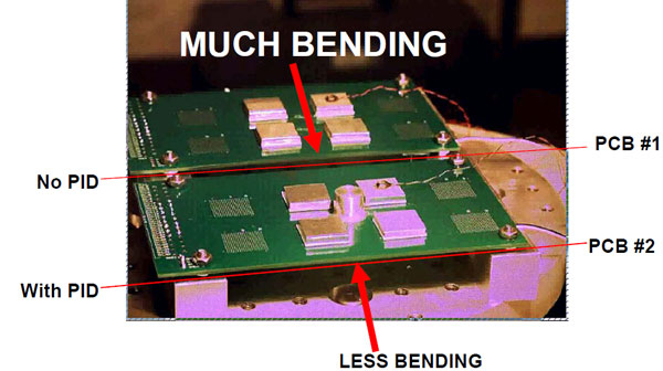
Vibration at the fundamental frequency fo causes bending, fatigue and cracks in the PCB assembly. Excessive vibration from external excitations lead to catastrophic failure. NASA invented PID technology to reduce vibration and increase reliability in circuit board assemblies.

PID are commercially available COTS components. Mounting methods include: standard surface mount soldering, BGA, screw mounting and epoxy mounting with permanent adhesives. Engineering development kits are available.


PID Simulation
  •  Card Simulation


Schematic
Particle Damper
Single Degree of Freedom

PID technology works without batteries or electrical power. The motion of the tungsten balls in the sealed PID housing removes vibratory energy from non-linear vibroacoustic environments such as PCB card assemblies. Losses and damping occur during impacts between the tungsten balls and the walls. The PID straightens the PCB at the central lobe and attenuates vibration by pushing and pulling the PCB in the opposite direction after the tungsten balls overcome gravity. PID is also suitable for tuned beam fixtures.

Schematic of PID and System
M = Mass of Card Assembly
K = Stiffness of Card at fo
C= Inherent Damping of Card
mp = Mass Tungsten Balls in PID


Inspired by Gravity®


Simulation of Particle Impact Damper


Weibull Failure Analysis #1
A destructive life test was performed on NASA's Marshall Space Flight Center printed circuit card assemblies 4" x 7" (10 x 18cm) 0.090-inch (2.3mm) thick. Four 21mm x 21mm daisy-chained 400-I/O CCGA column grid array components were mounted on each card. One card was left undamped. A PID damper was epoxy mounted at the center of the second card. The cards were mounted side by side onto a vibration table and subjected to excessive vibrations. 19 channels on the undamped boards (without PID) failed within 12 minutes. By comparison, 19 channels on the damped boards (with PID) survived 5 hours (306 minutes) before ultimately failing. See YouTube Video.


Weibull Failure Analysis #2
Comparison was made between assemblies of two different card thickness: 0.070-inch (1.78mm) versus 0.090-inch (2.3mm). Card size 4" x 7" (10 x 18cm). 8 assemblies total. 4 assemblies of each thickness. Four 21mm x 21mm daisy-chained 400-I/O CCGA column grid array components were mounted on each card. 2 cards of each thickness were left undamped. A PID particle impact damper was epoxy mounted at the center of the other cards. Cards of same thickness were mounted side by side onto a vibration table and subjected to excessive vibrations. A channel failure was defined as a total increase in resistance greater than 1000 Ohms connected through 100 I/O columns during vibration testing. The time for each failure was recorded. A Weibull analysis of channel failures for damped and undamped boards of two thicknesses was recorded. In all cases, damped assemblies with PID survived longer. The damped thinner boards (0.070-inch) with PID survived longer than the undamped thicker board (0.090 inch) without PID. See NASA study Demonstrating Effect Particle Impact Damper

Acceleration measured
during Weibull Failure Analysis #2
Comparison of undamped and damped assembly.
Strain Spectral Densities measured
during Weibull Failure Analysis #2
Comparison of undamped and damped assembly.
 

Outline Drawing (PDF)
TYPICAL PID OUTLINE
Example layout of PID as a development kit. The housing consists of a cylindrical canister. The threaded PID housing is screwed onto the flange mounted near the geometric center of the board. A small plugged hole at the top of the canister allows tungsten balls to be added or removed. The payload of tungsten balls is determined while observing vibration damping (attenuation). A final design can be fabricated for volume production after optimizing the system.
 

Tungsten Balls
Property of Tungsten

Tungsten (W) is an environmentally friendly substance of high density and tensile strength that can fully function at extremely low and very high temperatures.

  • Atomic Number 74
  • Density 19.3g/cc (@20°C)
  • Linear CTE 4.3 ppm/deg;C
  • Poisson's Ratio 0.284
  • Melting Point 3400°C
  • Tensile Strength 700~3400 MPa @25°C


  • Weights and Measures:
  • Size: Ø2.0mm
  • Weight 0.07405 gm each
  • 13,500 balls per kg

  • Size: Ø0.079"
  • Weight 0.00016315 lbs each
  • 6131 per lbs
  •  


    Part Numbering System
        F         A         1.0         SQ         13x4.0         Rev    
    Series Mounting
    on PCB
    Tungsten Payload
    Grams
    Exterior Shape Size (mm)
    Max
    Version/Option
    Series   •   Description

    STANDARD PID (Filled)
    F = FR4 Case

    Other:
    A = Aluminum Case

    Empty (Tunable) PID
    E = FR4 Single Layer
    K = Engineering Kit

    Hardware & Accessory
    B = Bridge

    CodeType

    STANDARD:
    A  =  Adhesive
    Glue/Epoxy

    OTHER:
    S  =  Screw
    WeightGrams

      Empty
    0.1 = 0.1 gm
    0.5 = 0.5 gm
    0.9 = 0.9 gm
    1.0 = 1.0 gm
    2.5 = 2.5 gm
    5.0 = 5.0 gm
    10 = 10 gm
    25 = 25 gm
    50 = 50 gm
    100 = 100 gm
    200 = 200 gm
    400 = 400 gm
    500 = 500 gm
    999 = 999 gm

    Other Mass Available
    CodeShape

    SQ = Square

    R = Rectangular
    C = Cylindrical
    T = Toroidal
    Z = Custom
    SQUARE
    X/YHeight
    13 x 4.0
    19 x 4.5
    25 x 5.0
    35 x 6.5
    45 x 10
    Other Sizes Available


    Rectangle
     X  Y Z
    13 x 20 x 4.0
    19 x 25 x 4.5
    25 x 32 x 5.0
    32 x 50 x 10
    Other Sizes Available


    Option-Rev
    CodeVersion
    A • 01
    B • 02
    C • 03
    Z • 26
    - - - -
    BA • 27
    BB • 28
    BC • 29
    BZ • 52
    - - - -
    CA • 53
    CB • 54
    CC • 55
    CZ • 77
    - - - -
    DA • 78
    DB • 79
    DC • 80
    DU • 99
     
     
    Filled Drawing Number System
     
        1         3         591         1    
    Series Mount Style Mass (gm)
    9 = Decimal Point
    Option Code
    CodeItem Description

    STANDARD:
    1 = PID
    Filled & Sealed

    OTHER:
    2 = TBA
    3 = TBA
    4 = TBA
    CodeDescription

    STANDARD:
    3 = Adhesive (FA)

    OTHER:
    2 = Screw (FS)
    9 = Custom
    CodeWeight
    001~008 = Accessory
    — — —
    908 = 0.08 gm
    912 = 0.12 gm
    948 = 0.48 gm
    962 = 0.62 gm
    993 = 0.93 gm
    — — —
    190 = 1.0 gm
    197 = 1.7 gm
    295 = 2.5 gm
    591 = 5.1 gm
    792 = 7.2 gm
    — — —
    010 = 10 gm
    017 = 17 gm
    024 = 24 gm
    030 = 30 gm
    052 = 52 gm
    — — —
    100 = 100 gm
    150 = 150 gm
    200 = 200 gm

    Code 9 = Decimal

    Other Mass Available
    Filled/Sealed
    CodeOption
    1 = Option A
    2 = Option B
    3 = Option C

    Other Options Available
     
     
    Empty Drawing Number System
     
        7         3         35         01    
    Series Mount Style Package Type Option Code
    CodeItem Description
    5 = Engineering Development Kit
    6 = Interposer Bridge
    7 = Empty Cavity Package
    9 = Hardware & Accessories

    CodeDescription
    2 = Screw
    3 = Adhesive
    9 = Custom
    0 = Outline DWG
    CodeSize
    07 = 7mm
    08 = 8mm
    09 = 9mm
    10 = 10mm
    13 = 13mm
    15 = 15mm
    17 = 17mm
    23 = 23mm
    25 = 25mm
    27 = 27mm
    35 = 35mm
    37 = 37.5mm
    40 = 40mm
    42 = 42.5mm
    45 = 45mm
    47 = 47.5mm
    50 = 50mm
    52 = 52.5mm
    55 = 55mm
    60 = 60mm

    More Sizes
    Available
    CodeOption
    01 = Option A
    02 = Option B
    03 = Option C
    04 = Option D
    05 = Option E
    06 = Option F
    07 = Option G
    08 = Option H
    10 = Option J
    11 = Option K
    12 = Option L
    13 = Option M
    14 = Option N
    16 = Option P
    17 = Option Q
    18 = Option R
    19 = Option S
    20 = Option T
    21 = Option U
    22 = Option V
    23 = Option W
    24 = Option X
    25 = Option Y
    26 = Option Z
    CodeOption
    27 = Option BA
    28 = Option BB
    29 = Option BC
    30 = Option BD
    31 = Option BE
    32 = Option BF
    33 = Option BG
    34 = Option BH
    36 = Option BJ
    37 = Option BK
    38 = Option BL
    39 = Option BM
    40 = Option BN
    42 = Option BP
    43 = Option BQ
    44 = Option BR
    45 = Option BS
    46 = Option BT
    47 = Option BU
    48 = Option BV
    49 = Option BW
    50 = Option BX
    51 = Option BY
    52 = Option BZ
    CodeOption
    53 = Option CA
    54 = Option CB
    55 = Option CC
    56 = Option CD
    57 = Option CE
    58 = Option CF
    59 = Option CG
    60 = Option CH
    62 = Option CJ
    63 = Option CK
    64 = Option CL
    65 = Option CM
    66 = Option CN
    68 = Option CP
    69 = Option CQ
    70 = Option CR
    71 = Option CS
    72 = Option CT
    73 = Option CU
    74 = Option CV
    75 = Option CW
    76 = Option CX
    77 = Option CY
    78 = Option CZ
    CodeOption
    79 = Option DA
    80 = Option DB
    81 = Option DC
    82 = Option DD
    83 = Option DE
    84 = Option DF
    85 = Option DG
    86 = Option DH
    88 = Option DJ
    89 = Option DK
    90 = Option DL
    91 = Option DM
    92 = Option DN
    94 = Option DP
    95 = Option DQ
    96 = Option DR
    97 = Option DS
    98 = Option DT
    99 = Option DU

    Other Options
    Available
     
    ECCN: EAR99 Export Administration Regulations
    HS Code: 8542.90.0000 ELECTRONIC INTEGRATED CIRCUITS AND MICROASSEMBLY PARTS
    ITAR: Not Restricted.
     
    Download Solidworks® e-Drawing viewer to enjoy 360° rotatable models.
    For PC   •   MAC Version


    TopLine Corporation
    95 Highway 22 W
    Milledgeville, GA 31061, USA
    Toll Free USA/Canada (800) 776-9888
    International: 1-478-451-5000
    Email: sales@topline.tv

    ©2022 TopLine. All Rights Reserved.

    Home